A relay is an electromechanical switch which is used in industrial application to provide isolation between high voltage and low voltage circuits. These two circuits have a different voltage rating. One might be a low voltage side and another high voltage side. A relay is an electrical mechanical switch that is used for switching between 5-volt circuits and 220/ 120 Volt AC circuits. For example, in microcontrollers based circuits, the relay is used to isolate microcontrollers from 220 volt AC supply.
Components of an electromechanical relay?
Electrical mechanical relay has three main components:
- Coil
- spring
- contacts
A five volt signal at the coil can turn on a relay. When the coil is energized with a 5-volt signal, current flows through the coil. When current flows through the coil, a magnetic field is created in the coil which attracts causes the armature ( contacts) to attract towards spring. When no current flows through the coil, spring causes the contacts to pull towards the normal position. Circuit diagram of an electromechanical relay with components are given below:
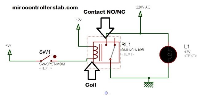
In the above circuit diagram, the 5-volt signal is given to the coil of an electromechanical relay, when the switch is closed, current flows through the coil and energizes the coil. When coil energizes through 5-volt signal, spring attracts contact form normally open position to closed position. On the left-hand side of the coil is normally an open position of contact. Because the circuit is no complete or in other words current flow path is not complete. When the coil is energized with the help of 5-volt signal, internal spring of electromechanical relay attract or pulls contact towards other point and complete the circuit.
An electromechanical relay can be either normally open or normally closed. In the above circuit diagram, a Normally open electromechanical relay is used. A voltage required to energize the coil, vary from the relay to relay. Voltage may vary from 5 volts to 50 volt and current may vary from mA to 20mA. The relays also have a minimum voltage rating. It means the below voltage rating relay will not operate. One can check the minimum operating voltage o relay in its datasheet. But current requirements are not specified in date sheets. Coil resistance is usually provided in the datasheet of a relay which can be used to find the current requirement of the relay using Ohm's law formula V= IR. After getting a basics understanding of relay, now you can understand what is relay driver and how to use relay driver circuit IC ULN2003?
What is relay driver circuits IC?
Relays are used mostly interfaced with microcontrollers and digital systems. But microcontrollers usually can not provide enough current to drive relays. Microcontroller pins usually provide a maximum current of 1-2 mA per pin which is not enough o operate relay. The circuits which are used to derive relays are called relay driver circuits. Therefore Relay driver circuits using ULN2003 are used to drive relays. There are many other ways to operate relays. I will also discuss other methods of relay driver circuits in the later part of this article.
Why do we need to use relay driver circuits?
While working on electronics projects which used a microcontroller, we need to use relays to control AC loads or high voltage loads. Relays are used to provide isolation between microcontroller's circuits and high voltage operating loads. Microcontrollers are only used to provide on/off signals to relays. Microcontrollers don't have enough current sourcing ability to derive relays. Therefore relay driver circuits IC is used to derive relays properly. There are many ways to design relay driver circuits. But dedicated relay driver circuits integrated circuits are available which serve the purpose of relay driver IC. Relay driver circuit IC ULN2003 is one of the popular relay driver circuits. I will discuss relay driver IC ULN2003 in this article. Following types of relay driver circuit IC's are also available in the market:
- ULN2003
- CS1107
- MAX4896
- FAN3240
- A2550
Relay driver circuit using Transistor
The relay driver circuit using an NPN transistor is given below. Transistor is used as a switch in this circuit. The microcontroller provides High or low input signals to NPN transistors. NPN transistor provides high driving current to electromechanical relay through the 12-volt external power supply.

Following components are used in relay driver circuit using transistor:
- Base current limiter resistor R1 = 1K
- Zener diode of 12 volts used as a freewheeling diode
- NPN transistor
- 12-volt dc power supply
- Electromechanical relay rating depends on your requirement of load
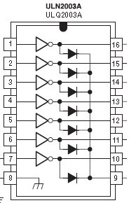
Pinout ULN2003

Relay driver circuit using ULN2003
ULN2003 is a very famous relay driver integrated circuit. Relay driver IC uln2003 is high voltage and high current integrated IC which used Darlington array. Its contains seven Darlington pair of a transistor which have high voltage and high current carrying capability. Its mean ULN3002 can drive up to seven relays at a time. A diode is used with each pair of NPN Darlington transistor. Diode makes it easily useable with inductive loads.
Applications of relay driver IC using ULN2003
There are many applications of a relay driver circuit using uln2003, but some of the famous applications are given below:
- relay drivers circuits
- motor drivers circuits
- lamp drivers
- line drivers
- hammer drivers
- logic buffers and many others
Diagram of relay driver circuit using uln2003
The relay driver circuit using uln2003 is given below. In this circuit diagram, the pic microcontroller is providing a signal to 4 relays through relay driver IC uln2003.
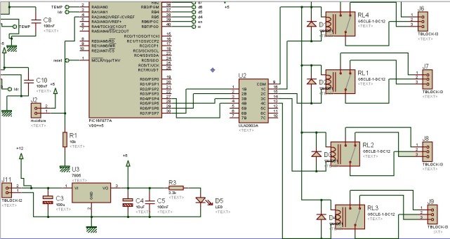
if we make the above circuit diagram using transistors, it will be very difficult to design this circuit. Single ULN2003 can be easily used int this circuit to drive up to five relays. Microcontrollers can easily provide a high or low signal to relays through its output port D. Simple programming instructions tells the microcontroller to provide either high or low signal to relays. According to signals provided by a microcontroller, ULN2003 IC drive relays.
I have posted a project on the greenhouse system in which the relay driver circuit using uln2003 is used to drive four relays. Four relays are connected with four different relays. Check the following link to know more about the practical use of relay driver circuit:
Intelligent green house control system
Stepper motor interfacing using Uln2003
While interfacing stepper motor with microcontrollers, relay driver circuit using uln2003 is also used. Its circuit diagram using pic microcontroller is given below:
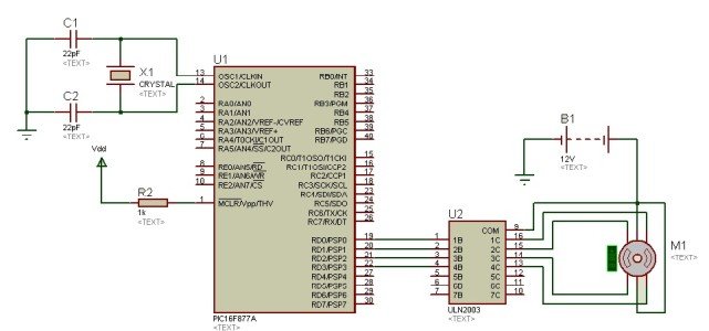
Schematic of a relay driver circuit using uln2003
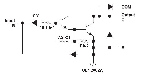
Internal circuit diagram of relay driver ic Darlington pairs is given below. A clamped diode is used as a freewheeling diode to avoid back emf effect in case of inductive loads.
Each output pin of ULN2003 provides up to 500mA current and peak current of 600mA. So this is all about relay driver circuit using uln2003. If you feel any issue while using uln2003 IC in your project, can you write in comments?
Source: https://microcontrollerslab.com/relay-driver-circuit-using-uln2003/
Posted by: davidhileaveaep.blogspot.com

Posting Komentar